Due to a synology update the DDNS field was cleared – site is now available again.
Blog back up
Due to NAS problems the blog was down for a few days. Apologies for the inconvenience.
SVG / DXF files for R204 / R175 cyclinder and head gaskets
SVG files for laser cutting R204 / R175 gaskets added under documents section.
Spare parts list for GTS 50
Added the spare parts list for the GTS50 Typ 517-39 L0/40 L0 under documentation.
New spare parts list
Scans added for the 442 automatic, DB 201 and KS 601 in the documentation section.
New spare parts list added for Bella R200
New spare parts lists added in German for the Bella R200 here: Spare Parts Lists
Zundapp citation – Horex Imperator Spare Parts List
Added the spare parts list for the Zundapp Citation (same as Horex Imperator)
Blog back on line
Blog back up after a server move.
High resolution tools brochure added
A high resolution version added of the original tools brochure:
And an English version of the Zundapp 200S user manual – Operation and Maintenance here:
Wiring up the starter switch
Steps to install the ignition switch in the sick patient bike:
- Put the protective cover back on the switch (chromed cover with black slider on it, left next to entrance to your garage
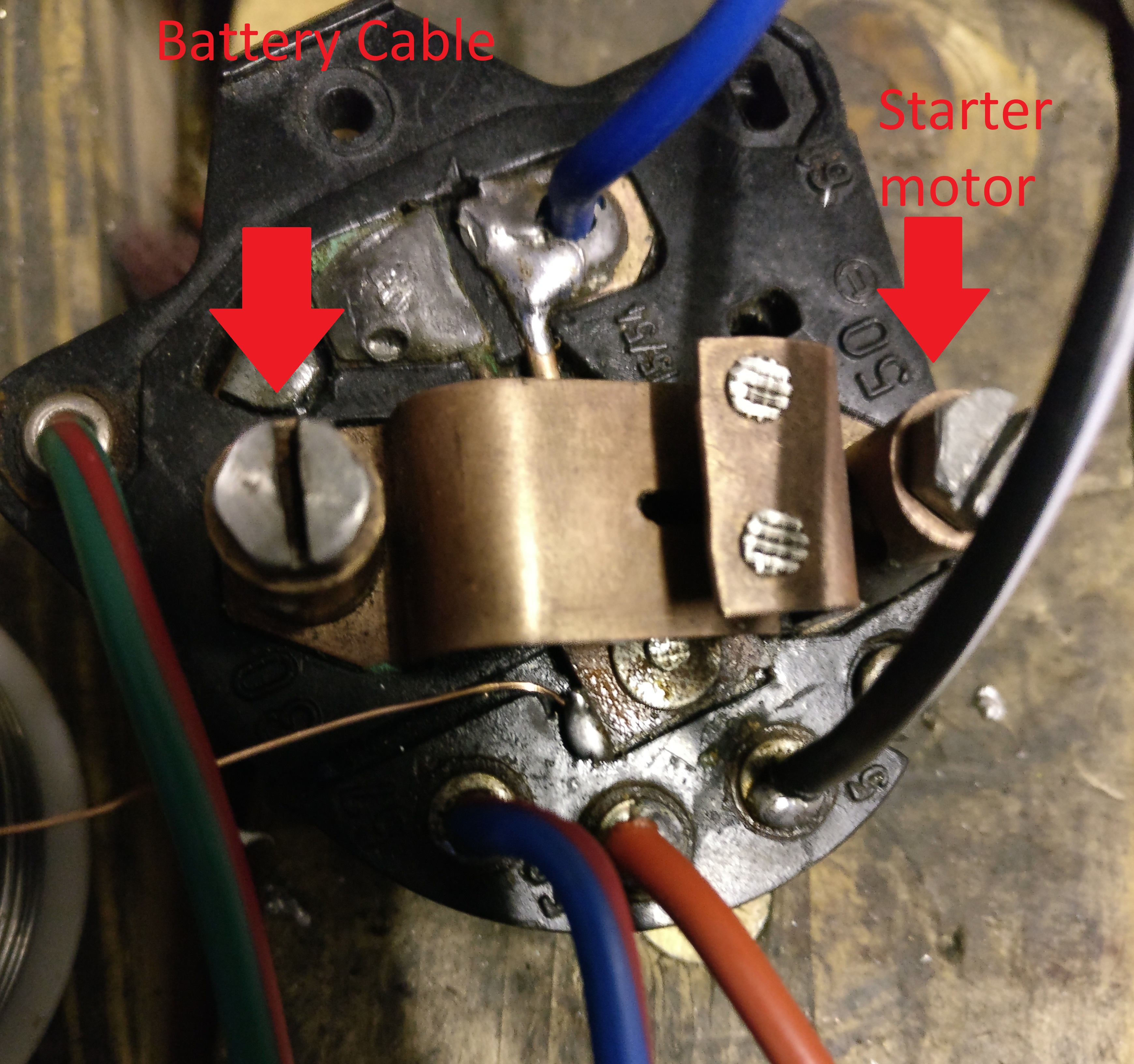
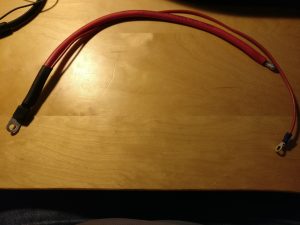
- Connect the red wire from the starter motor to the right hand side of the switch looking towards it, connect the cable from the switch to the positive terminal of the battery to the left hand side of the switch (do not connect it yet to the battery!):

- Screw the starter switch into place in the dashboard
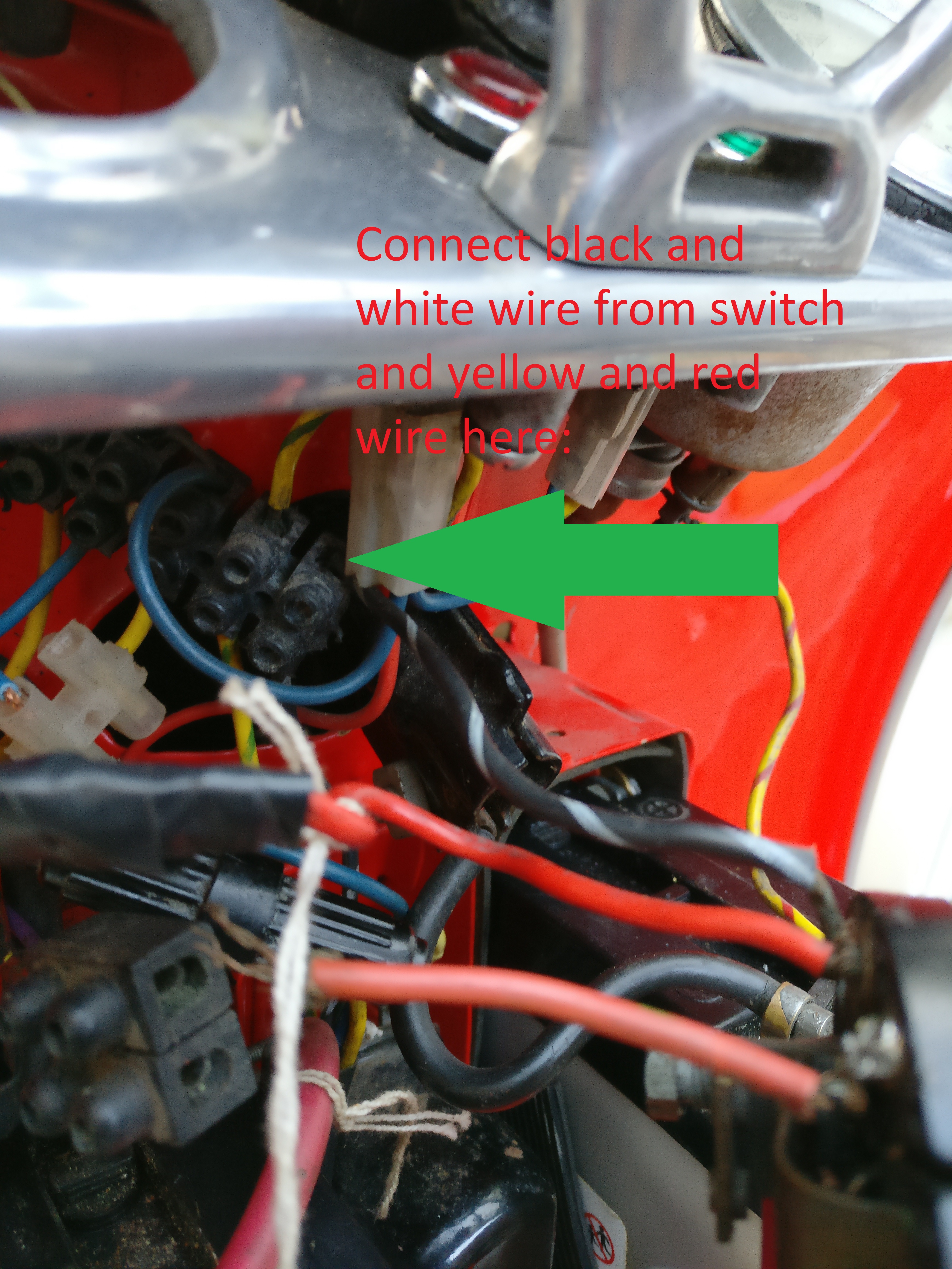
- Connect the black and white wire from the starter switch as well as the red and yellow wire from the speedometer light to the top right connector of the connecting bridge:
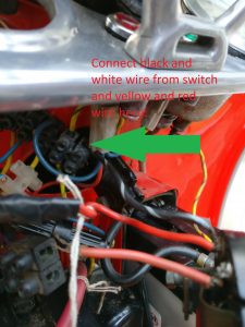
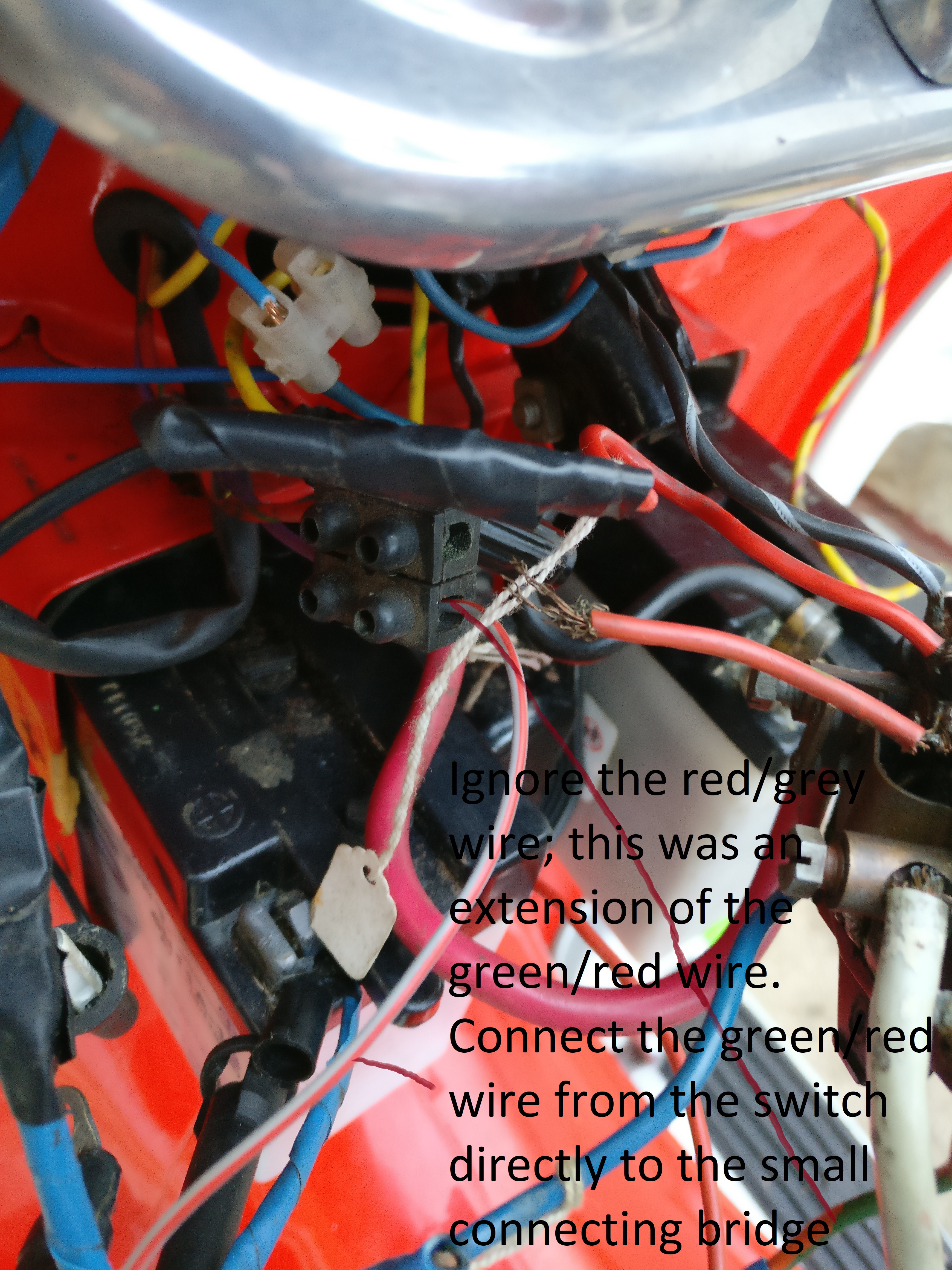
- Connect the green / red wire from the switch to the small connecting bridge. This connects to the parking light. The grey / red cable that was previously there was just an extension of the green / red wire and is now replaced by a proper wire (note: the bridge appears to be wired in reverse from spec with green/red connecting to purple rather than green/red, but as that is what it was, you can try it):

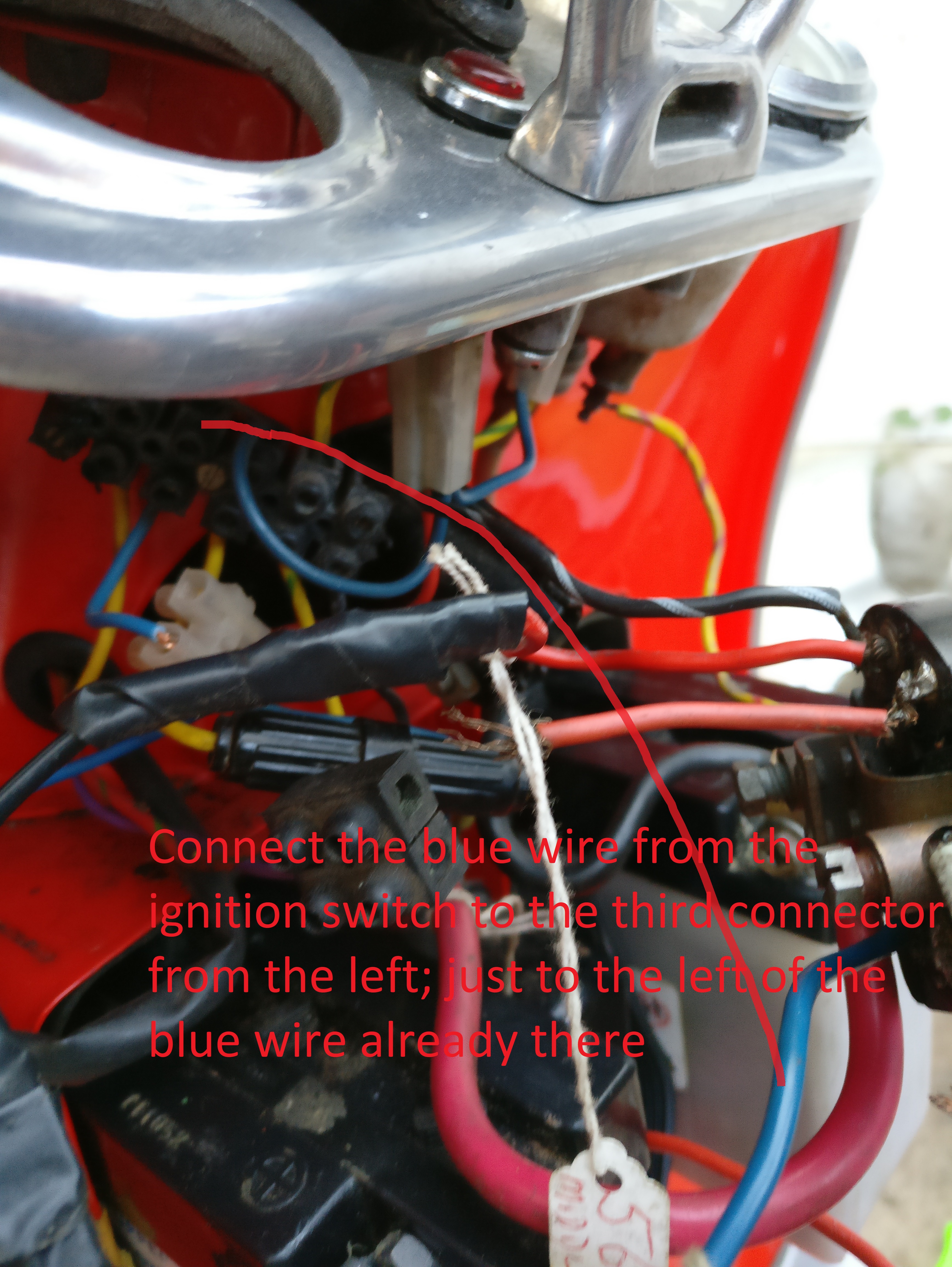
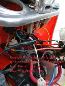
- Connect the blue wire from the ignition switch to the top row, third from the left empty slot in the connecting bridge:
- Connect the smaller red wire that splits from the battery connection to the regulator:
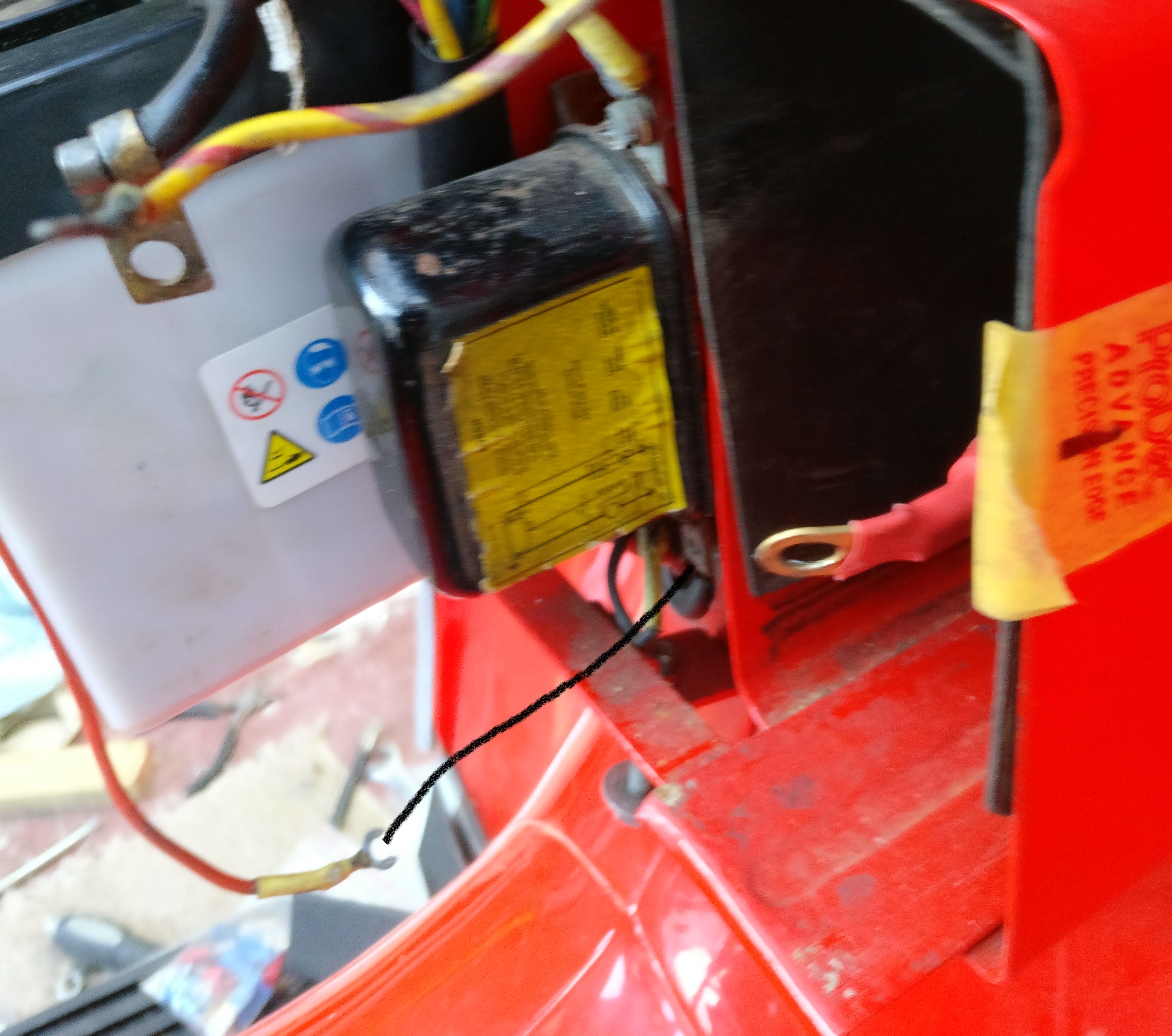
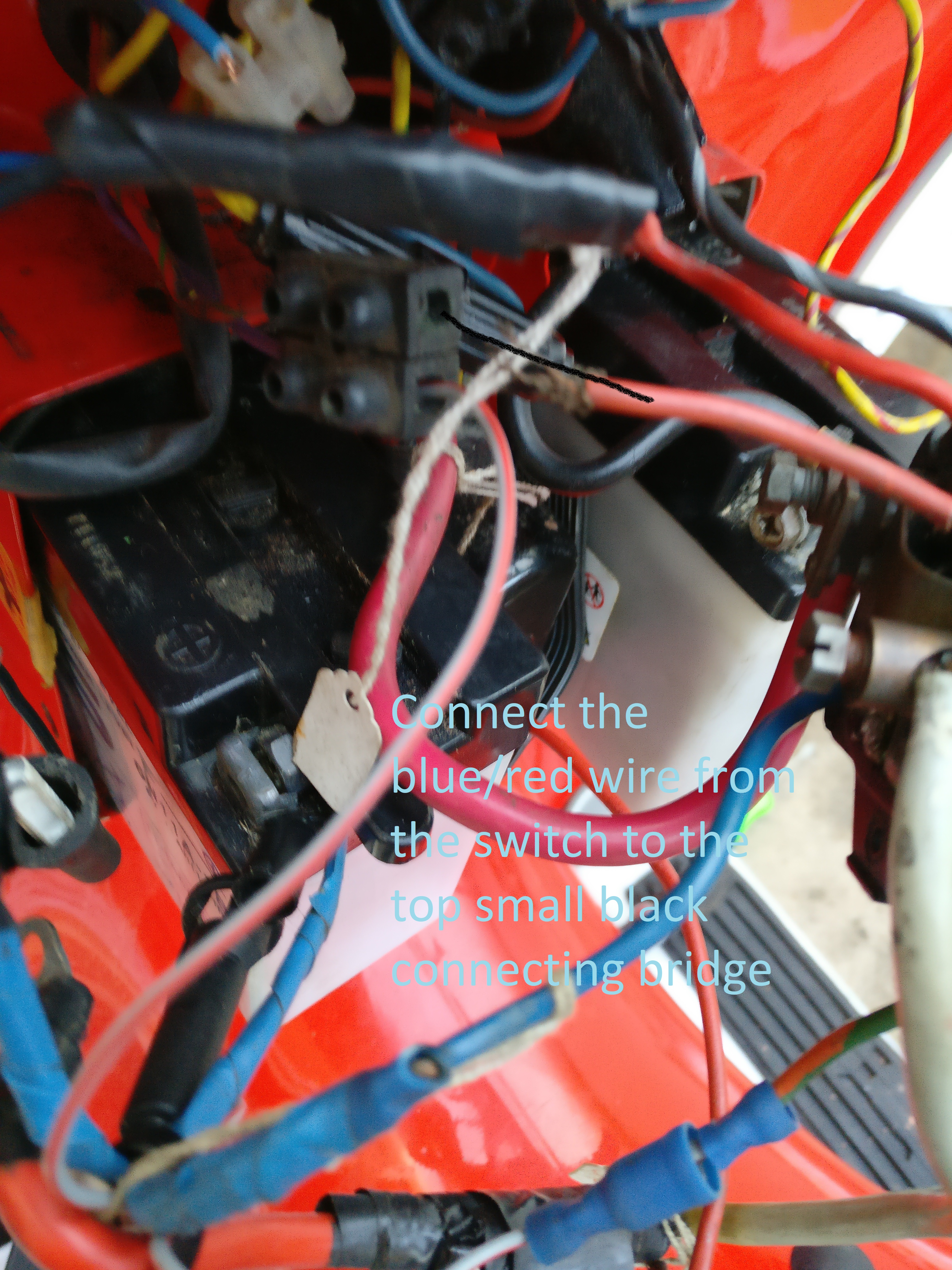
- Connect the blue/red wire from the switch to the other half of the small black connecting bridge to which the red/green wire is now already connected.

- Connect the red wire from the ignition switch to (TBD)
- Check whether the two wires coming into the small black connecting bridge have been soldered at the ends; if not: do so.
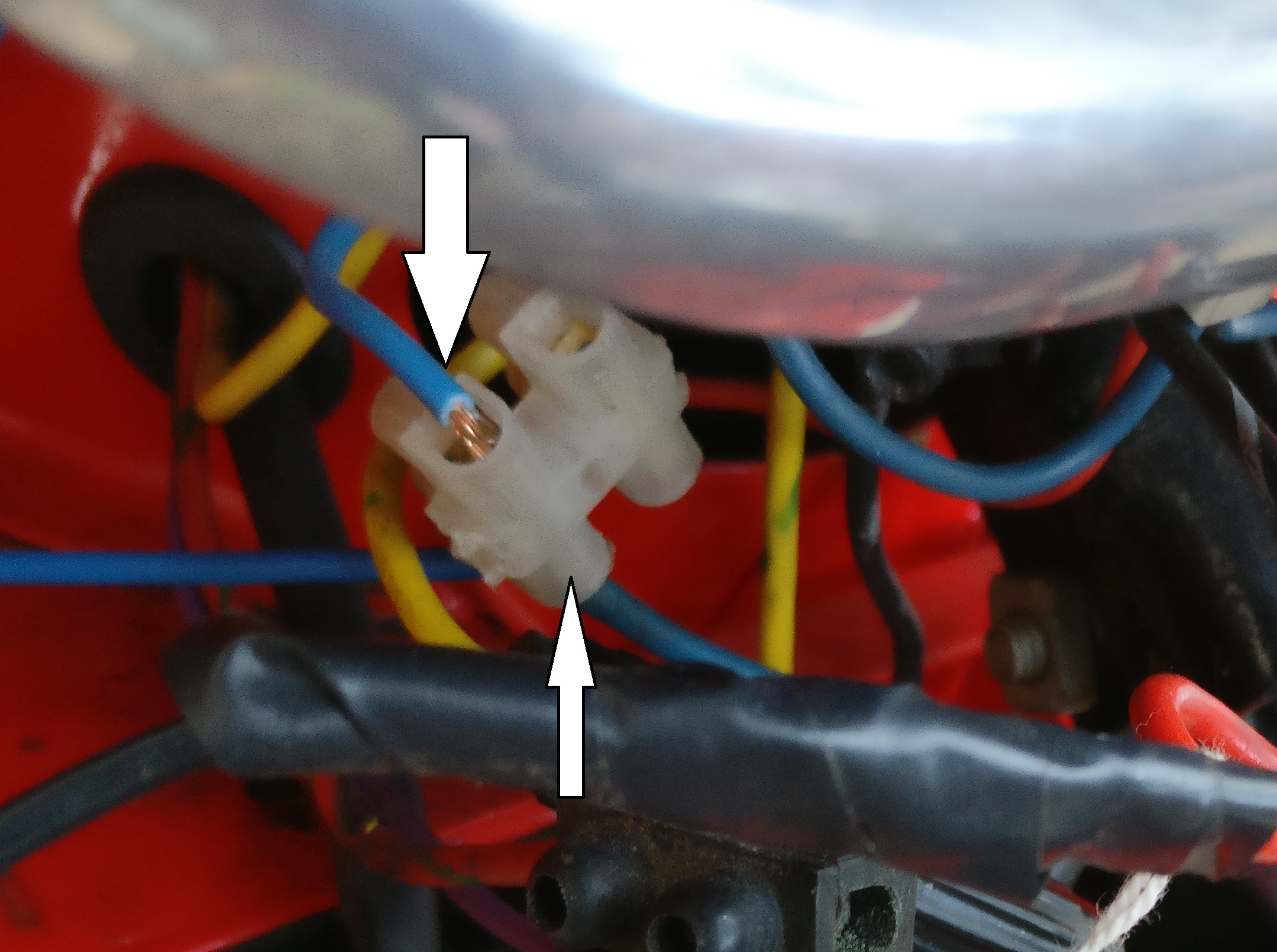
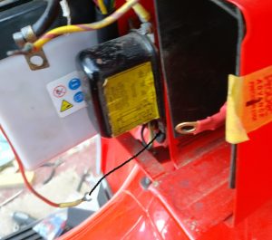
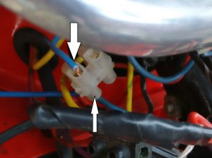
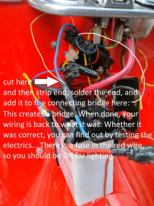
- The blue wire coming from the ignition coil goes into a transparent small connecting bridge. Take the bridge out, put a length of shrinktube on the lower end. Solder both ends together and solder the end going into the long black connecting bridge. When done, use a heatgun (paintgun) or a lighter to shrink the shrinktube by heating it. This will create a nice solid blue wire instead of having to use a connecting bridge. Before you start: check that the total length is long enough to get to the connecting bridge. The second blue wire coming in from the bottom should be leaded as well and doubled up in the long black connecting bridge. Alternatively, just lead the cable ends and re-use the white connecting bridge.
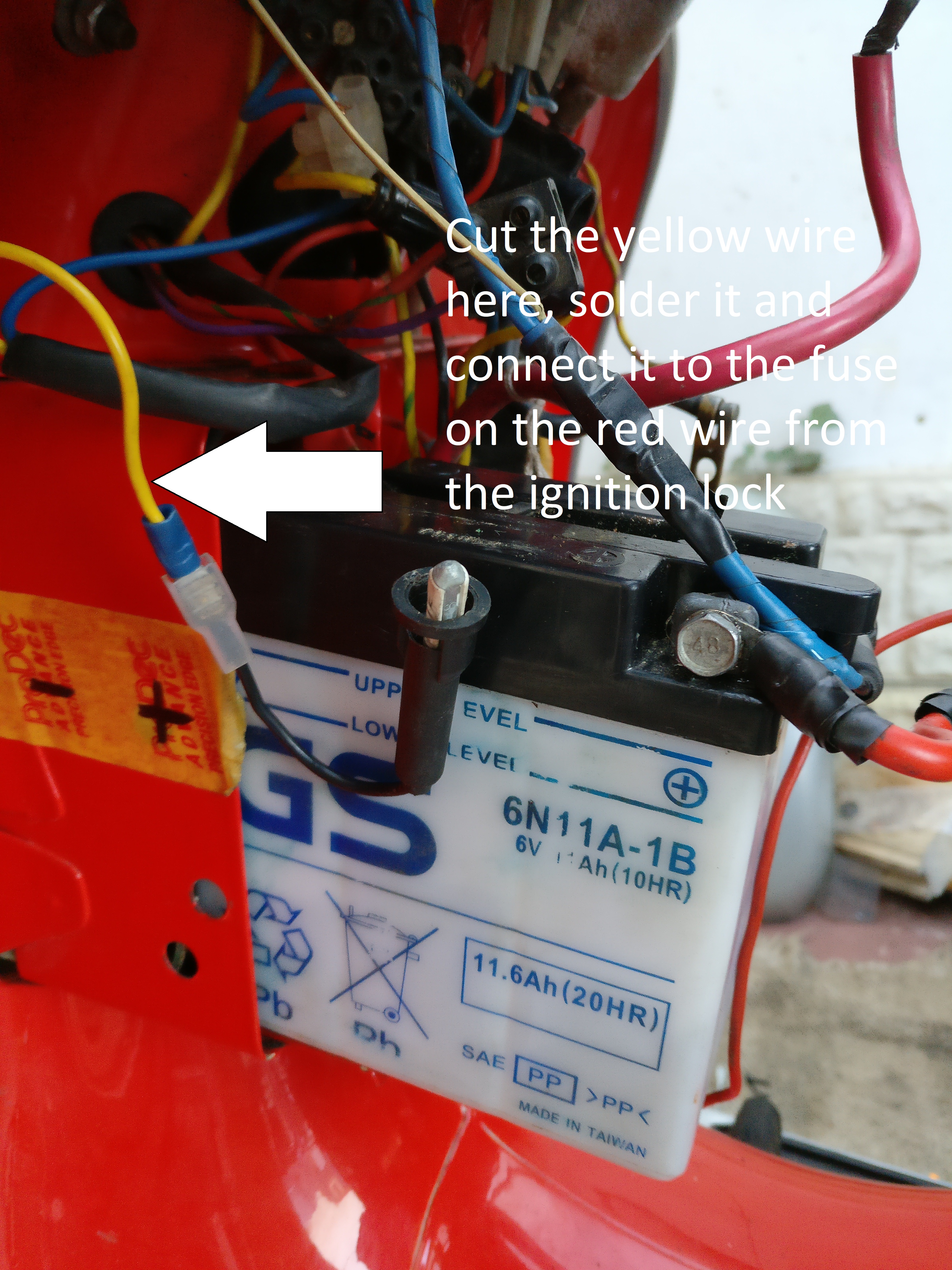
- The red cable from the ignition lock should be connected to the yellow cable here:

- Solder the thin wire as follows:
- Check all other connectors whether they have soldered ends and if not, solder them (e.g. the yellow wires going into the fuse).
- Hook up the red battery cable
- Check lights and horn
- Press the start button.
- Report back :-).